In this article, you will get all the basic information about ‘’How to calculate tolerance in engineering’’ and the various terms involved in measuring tolerance.
When a machine is made it is not made entirely in one go. It often includes many parts which needs to fit well to assemble it. Es the individual parts go together with other parts which essentially will end up becoming a fully assembled machine, these parts need to be perfectly measured in order to fit with each other and work properly. These fits need to be controlled under some standards, with defined tolerances.
Tolerance Terms and Their Definitions
- Normal size: This term is used for general size descriptions. For example 5/6 in shaft, 31 mm shaft, etc.
- Tolerance: Tolerance is which allows parts to fit rightly with each other enabling the machine to work properly. The variation in lower & upper limit dimensions is equal to tolerance. e.g., if the lower dimension is 0.500 and the upper dimension is 0.505, then the tolerance would be 0.005.
- Limit dimension: It is permitted size for lower & upper feature dimensions e.g. 0.505-0.500, where 0.505 is lower limit dimension and 0.500 is the upper limit dimension.
- Fit: A fit is what describes the range of tightness assemble of parts to keep them set and function correctly. A fit can be explained in 3 categories.
- Clearance Fit
- Force Fit
- Transition Fit
- Basic hole system: This is the system in which the basic size of a hole appears as one of the limit dimensions of the hole.
- Basic shaft system: This is the system in which the basic size of a shaft is included in one of the dimension limits.
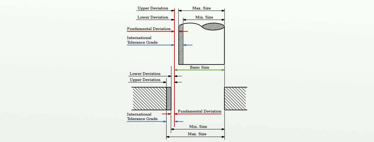
- Fundamental deviation: A fundamental deviation is an allowance. It is the deviation among the hole minimum diameter & shaft maximum diameter. There are a total of 25 deviations available to calculate tolerance. These deviations are alphabets which are used for holes and shafts. Block letter represents holes and small letters are used to represent shaft.
- Tolerance grade: Tolerance grade determines the tolerance of the given machinery’s limit and fits. Different grades are used for different types of engineering.
- IT01 to IT4: This tolerance grade is used to produce gauges, measuring instruments and, plug gauges.
- IT5 to ItT7: This grade is used to measure fits in engineering applications.
- IT8 to IT11: This grade is used for general engineering.
Process on how to calculate tolerance in engineering
First, we need to calculate the fundamental deviation for shafts and then for holes. As I mentioned above, tolerance is the difference between the maximum and minimum limit dimensions. The minimum and maximum limit dimensions are upper and lower limits.
The calculation for tolerance can be done using the ISO system too. ISO system has done everything for us and a chart is used to sedlect the fit.
- Choose a fit you want for your machinery. The chart starts with loose-fitting where parts will move freely to tight-fitting where the hole will be expanded with heat to let the shaft in.
- After you have chosen a fit for the machine. You need to choose a code to support your fit. This chart has micro-level differences.
- Since its CNC (computer numerically controlled) these tolerances can be achieved during manufacturing.
So with a tolerance calculator, it is this easy. The tolerance definition for ISO 286-1 (2010) is applicable for sizes from 0 mm to 3150 mm.


